In this final part of the Red Hat Linux cluster series we will create resources and then group them into services that will be managed by our cluster. If you are joining this series at this point you may want to check our other guide for RHEL/CentOS 7 and above.
First, let's begin by adding our quorum device to the configuration. However, before we can do that we will need to start the ricci service. Do the following on both nodes. You may skip any steps that are repeated as this was previously covered in Part 2 of the series.
service ricci start
Next provide a password to the ricci user account that will be used by the ricci daemon when syncing the configuration across nodes.
passwd ricci
To test this we will synchonrize and activate our basic configuration on node1. This will result in the configurtion file being generated on node2.
ccs -h node1-hb --sync --activate
Now go over to node2 and verify that the configuration file is present.
cat /etc/cluster/cluster.conf
If there is an error verify that the ricci password is correct and ensure that there are no syntax errors in the XML. In the event that it still fails disable the firewall on both nodes with the below and retry.
service iptables stop
service ip6tables stop
Errors will be logged in the system message file /var/log/messages and under the directory /var/log/cluster/.
Starting the Linux cluster services
Once the configuration is synchronized the next step is to start the cluster services in the following order.
service cman start
service clvmd start
service rgmanager start
Check to ensure that all the services start without errors and then update the OS configuration to autostart these daemons on every reboot.
chkconfig cman on
chkconfig clvmd on
chkconfig rgmanager on
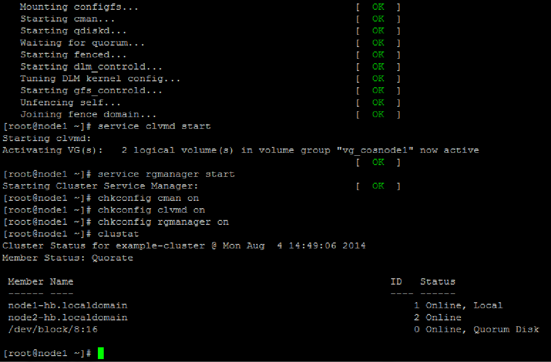
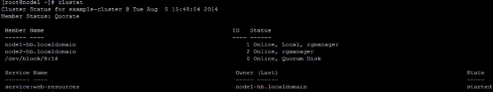
You should now have a running cluster similar to the below.
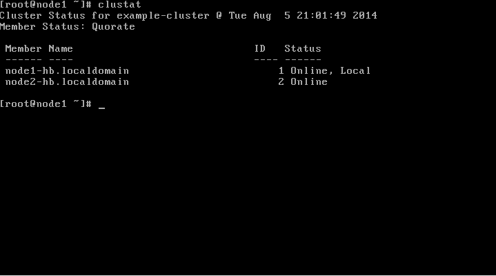
The cluster status can be verified from now on using the clustat command.
clustat
Although we have a running Linux cluster it is not very useful as it has no resources or services to manage. It's time to fix that by adding our quorum and creating a few resources.
Updating the configuration with the qdisk
Use mkqdisk to display the name of qdisk that will service as our quorum.
mkqdisk -L
We need to remind ourselves of the label as it will be referenced in our configuration file. Remember that a quorum device is a must for a two-node configuration but can be safely ignored for larger clusters.
ccs -h localhost --setquorumd label=clusterqdisk
Sets our quorum device in the cluster.conf at the end of which you will now see
<quorumd label="clusterqdisk"/>
Don't forget to synchronize the configuration using ccs at this point.
Creating the Linux cluster resources
Resources are the buidling blocks for the cluster. They are the atomic units in the cluster tree and form the leaves upon which service trees are comprised.
Clustered File Systems
To start off we will create the filesystems that will host our database data directory and the webserver's docroot.
Using fdisk -l remind yourself of the disk devices available to each node.
fdisk -l

Disk /dev/sda: 8589 MB, 8589934592 bytes
255 heads, 63 sectors/track, 1044 cylinders
Units = cylinders of 16065 * 512 = 8225280 bytes
Sector size (logical/physical): 512 bytes / 512 bytes
I/O size (minimum/optimal): 512 bytes / 512 bytes
Disk identifier: 0x000a50d6

   Device Boot      Start         End      Blocks   Id  System
/dev/sda1   *           1          64      512000   83  Linux
Partition 1 does not end on cylinder boundary.
/dev/sda2              64        1045     7875584   8e  Linux LVM

Disk /dev/sdb: 20 MB, 20971520 bytes
64 heads, 32 sectors/track, 20 cylinders
Units = cylinders of 2048 * 512 = 1048576 bytes
Sector size (logical/physical): 512 bytes / 512 bytes
I/O size (minimum/optimal): 512 bytes / 512 bytes
Disk identifier: 0x00000000


Disk /dev/sdc: 1073 MB, 1073741824 bytes
255 heads, 63 sectors/track, 130 cylinders
Units = cylinders of 16065 * 512 = 8225280 bytes
Sector size (logical/physical): 512 bytes / 512 bytes
I/O size (minimum/optimal): 512 bytes / 512 bytes
Disk identifier: 0x00000000


Disk /dev/sdd: 536 MB, 536870912 bytes
64 heads, 32 sectors/track, 512 cylinders
Units = cylinders of 2048 * 512 = 1048576 bytes
Sector size (logical/physical): 512 bytes / 512 bytes
I/O size (minimum/optimal): 512 bytes / 512 bytes
Disk identifier: 0x00000000


Disk /dev/mapper/vg_cosnode1-lv_root: 7205 MB, 7205814272 bytes
255 heads, 63 sectors/track, 876 cylinders
Units = cylinders of 16065 * 512 = 8225280 bytes
Sector size (logical/physical): 512 bytes / 512 bytes
I/O size (minimum/optimal): 512 bytes / 512 bytes
Disk identifier: 0x00000000


Disk /dev/mapper/vg_cosnode1-lv_swap: 855 MB, 855638016 bytes
255 heads, 63 sectors/track, 104 cylinders
Units = cylinders of 16065 * 512 = 8225280 bytes
Sector size (logical/physical): 512 bytes / 512 bytes
I/O size (minimum/optimal): 512 bytes / 512 bytes
Disk identifier: 0x00000000
Output similar to the above will be returned by fdisk on your local nodes. For our purposes in this lab we will focus on /dev/sdc and /dev/sdd which will serve as our data and docroot filesystems respectively.
Clustered LVM Configuration
There is no difference between regular lvm commands and clvmd commands. What this means is that we will still create Physical Volumes (PV)s then Volume Groups (VG)s followed by the Logical Volumes (LV)s.
However, prior to configuring volumes we need to update the locking_type parameter in the /etc/lvm/lvm.conf. The locking type value needs to be set to 3 on clustered systems.
    # Type of locking to use. Defaults to local file-based locking (1).
    # Turn locking off by setting to 0 (dangerous: risks metadata corruption
    # if LVM2 commands get run concurrently).
    # Type 2 uses the external shared library locking_library.
    # Type 3 uses built-in clustered locking.
    # Type 4 uses read-only locking which forbids any operations that might
    # change metadata.
    locking_type = 3
Restart the clvmd daemon on both nodes. Note that the cman service needs to be running.
service clvmd restart
Next create the PVs.
pvcreate /dev/sdc
pvcreate /dev/sdd
Next create the volume groups. Note, that when creating we specify the -cy option to mark these volumes as clustered.
 vgcreate -cy vg_example-cluster_data /dev/sdc
 vgcreate -cy vg_example-cluster_docroot /dev/sdd
Create the logical volume using the previously created clustered volume groups.
lvcreate -n lv_data -l 100%vg vg_example-cluster_data
lvcreate -n lv_docroot -l 100%vg vg_example-cluster_docroot
The logical volumes need to be activated.
lvchange -an vg_example-cluster_data/lv_data
lvchange -an vg_example-cluster_docroot/lv_docroot
Finally we create the mapper entries.
vgscan --mknodes -v
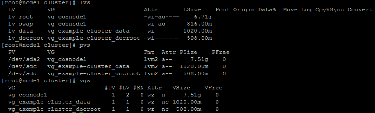
To verify the configuration use the pvs, lvs, and vgs commands on both nodes. Be sure to check that all the PVs, LVs, and VGs created above are present.
Creating GFS filesystem
Even though the underlying devices are clustered and are now accessible to the OS our applications cannot use the logical volumes as they still require a filesystem which is missing. All we have is logically managed raw devices at this point.
Throughout this tutorial we will use the GFS filesystem which has a high performance structure with in-built distributed locking mechanisms specifically designed for clustered environments utilizing a shared storage architecture.
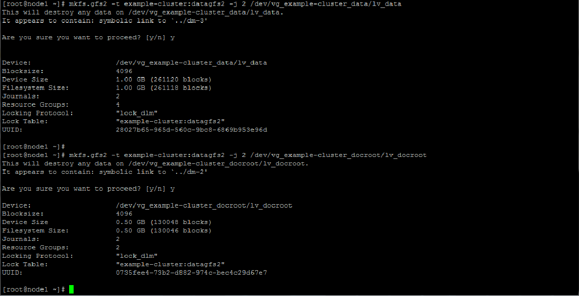
To create the filesystems do the following. The -t option format is
In the example below we use -j 2 -J 64 to create two 64-bit journals on the GFS. A seperate journal is needed per cluster node and our cluster is a two-node cluster so we will have only 2. Adjust as necessary for larger clusters.
mkfs.gfs2 -t example-cluster:datagfs2 -j 2 -J 64 /dev/vg_example-cluster_data/lv_data
and
mkfs.gfs2 -t example-cluster:datagfs2 -j 2 -J 64 /dev/vg_example-cluster_docroot/lv_docroot
Adding resources to the cluster configuration file
Updating the configuration with our freshly minted cluster filesystems is accomplished using the --addresource option of ccs.
ccs -h localhost --addresource clusterfs name=datagfs2 fstype=gfs2 mountpoint=/home/data device=/dev/vg_example-cluster_data/lv_data
and
ccs -h localhost --addresource clusterfs name=docrootgfs2 fstype=gfs2 mountpoint=/var/www/docroot device=/dev/vg_example-cluster_docroot/lv_docroot
The above adds the filesystems that will be mounted at /home/data and /var/www/docroot to our cluster.
You should now have resources in the Resource Manager <rm> section looking similar to the below in the cluster.conf.
<rm>
	<failoverdomains/>
	<resources>
		<clusterfs device="/dev/vg_example-cluster_data/lv_data" fstype="gfs2" mountpoint="/home/data" name="datagfs2"/>
		<clusterfs device="/dev/vg_example-cluster_docroot/lv_docroot" fstype="gfs2" mountpoint="/var/www/docroot" name="docrootgfs2"/>
	</resources>
</rm>
To complete our tutorial we are going to add one final resource to host our virtual IP address. This is the network address that will be shared with our clients making failover transparent to the external users.
All our resources will then be wrapped up into a service group called "web-resources." web-resources service group will first bring online our IP address after /home/data and /var/www/docroot are online.
Creating the VIP
Our virtual IP address wil be 192.168.10.4.
ccs -h localhost --addresource ip address=192.168.10.4 monitor_link=yes sleeptime=10
synchronize the configuration.
ccs -h localhost --sync --activate
Creating the "web" failover domain.
Failover domains determine which cluster members are allowed to run which services. They can be either ordered or restricted as well as provide a nofailback feature for services.
As this is a simple two-node cluster we will only have one unordered failover domain for all services called web.
ccs -h localhost --addfailoverdomain name=web
Creating the "web-resources" Service Group
Services are in essence just a bunch of related resources that are controlled as an atomic unit. Clusters manage services on nodes. The services are at the root of the resource tree. It is the services that are started and stopped and not resources.
ccs -h localhost --addservice web-resources domain=web recovery=relocate
Our resource tree is now taking shape.
<rm>
                <failoverdomains>
                        <failoverdomain name="name=web" nofailback="0" ordered="0" restricted="0"/>
                </failoverdomains>
                <resources>
                        <clusterfs device="/dev/vg_example-cluster_data/lv_data" fstype="gfs2" mountpoint="/home/data" name="datagfs2"/>
                        <clusterfs device="/dev/vg_example-cluster_docroot/lv_docroot" fstype="gfs2" mountpoint="/var/www/docroot" name="docrootgfs2"/>
                        <ip address="192.168.10.4" monitor_link="yes" sleeptime="10"/>
                </resources>
                <service domain="web" name="web-resources" recovery="relocate"/>
</rm>
The VIP address will be our parent resource which will depend on both filesystems. Therefore, the VIP will only be created if both filesystems successfully mount.
ccs -h localhost --addsubservice web-resources ip ref=192.168.10.4
Now let's add the filesystems as dependencies for the VIP.
ccs -h localhost --addsubservice web-resources ip:clusterfs ref=docrootgfs2
and
ccs -h localhost --addsubservice web-resources ip:clusterfs[0]:clusterfs ref=datagfs2
Pay careful attention to the order in which the service dependencies are added. Bear in mind that the cluster starts services from the bottom up. Hence, all leave nodes need to be started before the parent node can start.
Given, that most web applications will rely on the database we ensure that the /home/data is present before mounting /var/www/docroot.
        <rm>
                <failoverdomains>
                        <failoverdomain name="name=web" nofailback="0" ordered="0" restricted="0"/>
                </failoverdomains>
                <resources>
                        <clusterfs device="/dev/vg_example-cluster_data/lv_data" fstype="gfs2" mountpoint="/home/data" name="datagfs2"/>
                        <clusterfs device="/dev/vg_example-cluster_docroot/lv_docroot" fstype="gfs2" mountpoint="/var/www/docroot" name="docrootgfs2"/>
                        <ip address="192.168.10.4" monitor_link="yes" sleeptime="10"/>
                </resources>
                <service domain="web" name="web-resources" recovery="relocate">
                        <ip ref="192.168.10.4">
                                <clusterfs ref="docrootgfs2">
                                        <clusterfs ref="datagfs2"/>
                                </clusterfs>
                        </ip>
                </service>
        </rm>
Congratulations! You now have a working cluster to manage the web resources.
Conclusion
In the real world we would have actually had a service for the database and web server application.
Configuration changes would also have to be made on the application side to update web server's document root to point to the clustered filesystem and also to initialize the tablespace for the database to the datagfs2 shared filesystem.
However, these tasks have been deliberately left out and will serve as an exercise for the reader to do in his/her's own time. There are so many more options and features to explore. Challenge yourself.
I hope you enjoyed your Linux clustering crash course! :)
Series Recap
Part 1 and Part 2 or read our guide for those on RHEL/CentOS 7 and above.
Written by Nneko Branche.